5: Ladder Logic
TOPIC 1: Relay Logic
Before going forward, review how a relay works here.
Now that you understand the relay function let’s look at the way in which relays are typically drawn in relay logic.
Below is a seal circuit or a start/stop circuit. It is one of the most common circuits used in machine control. Both the start and stop switches are momentary which means they return to their normal state after you push them. The stop button is normally closed and the start button is normally open. There is one relay in the circuit consisting of both a relay coil and a relay contact. The contact is normally open.
When the start button is pushed it allows current to flow through the relay coil and forces the relay contact to become closed. Once the relay contact is closed there is an alternate path around the start button for current to flow so that when the button returns to its open position the current can flow through the contact and around the switch. When the stop button is pressed it interrupts current flow to the circuit and must be restarted again with the start button.

TOPIC 2: Ladder Logic Symbols
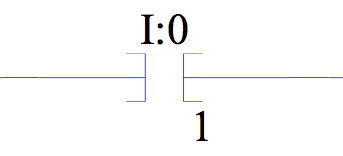
There are three main symbols we will use to begin with. These are the Normally Open (NO) Contact (also called the XIC – Examine if Closed), the Normally Closed (NC) Contact (also called the XIO – Examine if Open), and the output.

Normally Open Contact (XIC) – Address I:0/1 – input 1
Normally Closed Contact (XIO) – Address I:0/3 – input 3
Output – Address O:0/0 – output 0
With these three components, we can create the seal circuit in a ladder logic program. The first step is to realize that there are no switches inside the PLC, but instead a contact can be “associated” to an input and the switches can be wired to an input. For example, if a Stop Button was wired to input 1 and a Start Button was wired to input 2 the seal circuit might look light the following inside the PLC program.

In this program, a light is wired to output 0 (address O:0/0) and comes on when the start button is pressed. Additionally, there is a normally open contact associated with the light that will close when the output with the same address is on. So in this example, when input 1 (the stop button) and input 2 (the start button) go on, output 0 turns on and changes the state of the normally open contact called light. At this time there is now provided an alternate path for current to flow around input 2 (the start button). It is assumed that the externally wired stop button is normally closed and therefore I:0/1 is on (and the contact is closed) as long as the stop button is not pushed.
This program represents one “rung” of ladder logic code. Each level in the program is referred to as a rung like in a normal ladder. The lines that contain the program from the left and right are called rails.
TOPIC 3: Timers
Think of a timer in ladder logic as a traditional egg timer. You set it for a certain amount of time and when the time is up something happens. In order to accomplish this in the PLC, the timer uses up three words of memory. They are:
1. Word 0 – Timer Timing (bit), Timer Done (bit), Timer Enabled (bit), (the remaining 13 bits are for internal use)
2. Word 1 – Preset (word)
3. Word 2 – Accumulator (word)
There are three bits within word 0 that require further explanation
1. Timer Timing – This bit is on if the timer is currently timing. That is the timer has been started and it has not yet reached its final time.
2. Timer Done – This bit is on if and when the timer reaches its final time. This is the “ding” when the egg timer has reached zero.
3. Timer Enabled – This means that the timer has power and is capable of working. It may be timing or already done, but it has power.
Furthermore, there are two other pieces of memory that require further explanation
1. The Preset – The preset value is the time that the timer is timing to. It’s just like setting the egg timer for 15 minutes.
2. The Accumulator – This is the current amount of time that has passed since the timer started timing. When the accumulator reaches the preset the timer done bit comes on.
Each of these pieces of memory have their own address but first let’s discuss the timer address. The program can have many timers, each with its own general address T4:0, T4:1, T4:2, etc. This address should be considered the overall timer address. Down a bit deeper inside the timer there exist separate addresses for each part of the timer. We will assume that the overall timer address being used below is T4:3.
1. Timer Timing – T4:3/TT or T4:3/14
2. Timer Done – T4:3/DN or T4:3/13
3. Timer Enable – T4:3/EN or T4:3/15
4. Timer Preset – T4:3.PRE or T4:3.1
5. Timer Accumulator – T4:3.ACC or T4:3.2
One more important piece of information is the time base by which the timer is timing. There are three options here, 0.001 seconds (1mS), 0.01 seconds (10mS), and 1 second. In other words the accumulated value is interpretted as time only when the time base is known. If the accumulator is currently 324, it could mean 0.324S, 3.24S, or 324S depending on the selected time base.
There are three main types of timers
1. Timer, On-Delay (TON) – Works as described above.
2. Timer, Off-Delay (TOF) – Basically works the opposite of the above description.
3. Retentive Timer (RTO) – Works just like the TON but retains its accumulator even when disabled.
Here is an application of timers. First, observe that the first rung of code is the same as above with the exception that the start button is now wired to input 0. Also notice the rung number off to the left of the diagram. This program contains rungs 0 through 5.

There are two timers here, T4:0 and T4:3 each have a name given to them by the programmer, TIMER1 (T4:0) and TIMER2 (T4:3). Each are set to a time base of 0.01S. TIMER1 has a preset of 12,000 and TIMER2 has a preset of 18,000. Once the start button is pushed and the “LIGHT” goes on, the first contact on rung 1 closes (because it’s associated with output 0, the LIGHT). The second contact on rung 1 is normally closed. It remains closed until TIMER2 is done timing. Therefore, as soon as output 0 (O:0/0) turns on TIMER1 begins timing. As soon as it reaches its preset time, 120 seconds, the contact on rung 2 comes on and starts TIMER2. Continuing to rung 3 while TIMER1 is timing (that is, after the LIGHT is on and for 120 seconds after that) output 1 (O:0/1) is on. Similarly, while TIMER2 is timing (after TIMER1 is done and for 180 seconds after that) output 2 (O:0/2) is on.
At any time during operation, if the STOP button is pushed, causing the first contact in rung 0 to open, every rung is disabled, all timers reset, and all of the outputs are off. When a TON timer is disabled (current cannot get to it because a contact is open) it looses count and is reset back to zero.
TOPIC 4: Counters
Counters are similar to timers but instead of timing the passing of time they count events such as products passing on a conveyor or the number of bad parts rejected from a system.
Counters also consume three words of memory as follows.
1. Word 0 – Count Up (CU), Count Down (CD), Done (DN), Overflow (OV), Underflow (UN) (the remaining 11 bits are for internal use)
2. Word 1 – Preset (word)
3. Word 2 – Accumulator (word)
There are five bits within word 0 that require further explanation
1. Count Up (CU) – This bit is on if the counter is set to count up.
2. Count Down (CD) – This bit is on if the counter is set to count up.
3. Done (DN) – This bit is on if and when the counter reaches its preset.
4. Overflow (OV) – This bit is on if the count goes above the highest number able to be represented in the accumulator, 32,767.
5. Underflow (UN) – This bit is on if the count goes below the lowest number able to be represented in the accumulator, -32,767.
Furthermore, there are two other pieces of memory that require further explanation
1. The Preset – The preset value is the value that the counter is counting to.
2. The Accumulator – This is the current count that the counter has counted to. When the accumulator reaches the preset the done bit comes on.
Each of these pieces of memory have their own address but first let’s discuss the counter address. The program can have many counters, each with its own general address C5:0, C5:1, C5:2, etc. This address should be considered the overall counter address. Down a bit deeper inside the counter there exist separate addresses for each part of the counter. We will assume that the overall counter address being used below is C5:3.
1. Count Up (CU) – C5:3/CU or C5:3/15
2. Count Down (CD) – C5:3/CD or C5:3/14
3. Done (DN) – C5:3/DN or C5:3/13
4. Overflow (OV) – C5:3/OV or C5:3/12
5. Underflow (UN) – C5:3/UN or C5:3/11
6. Preset – C5:3.PRE or C5:3.1
7. Accumulator – C5:3.ACC or C5:3.2
There are two types of counters
1. Count up (CTU) – Counts from zero up to the preset value.
2. Count Down (CTD) – Counts down from the preset to zero.
Because counters always retain their count (because they are always enabled), there is another command we have to reset the current accumulated value. This is the RES command. The command looks like an output except you give it the address of the counter you wish to reset when the output is on. The RES command works to reset a timer also.
Here is an application of counters. Notice the rung number off to the left of the diagram. This program contains rungs 0 through 8.
 First, there is a sensor (really a switch) connected to input 0. This contact, on rung 0, comes on and back off again every time a product passes on a conveyor. The counter C5:0 (COUNTER1) counts these products as they pass. Once 100 products are counted the DN bit comes on and the contact on rung 1 closes. This causes OUTPUT0 (O:0/0) to come on. Additionally, the contacts on rungs 2 and 3 come on and cause COUNTER2 (C5:1) to count. It also starts a timer that times for 100mS. Once the timer is complete rung 4 countact T4:0/DN comes on and resets COUNTER1 (C5:0). Once this process occurs 4 times (400 parts have passed) the second counter, C5:1, reaches its preset. This turns on an output, O:0/1, on rung 5 and starts a 250mS timer on rung 6. Once this timer is complete, COUNTER2, C5:1, is reset on rung 7.
TOPIC 5: Other Common Ladder Logic Commands
There are a series of other commands that you will need to understand for use in the lab.
Math Commands
1. ADD – Takes two values and adds them together. Can be constant values or an address in memory.
2. SUB- Takes two values and subtracts them. Can be constant values or an address in memory.
3. MUL- Takes two values and multiplies them together. Can be constant values or an address in memory.
4. DIV- Takes two values and divides them. Can be constant values or an address in memory.
5. ABS – Takes the absolute value of a value in memory.
6. CLR – Clears, or sets to zero, an address in memory.
7. NEG – Takes the negative of a number.
Logic Commands
1. AND – The traditional AND logic function.
2. OR- The traditional OR logic function.
3. NOT- The traditional NOT logic function.
4. XOR- The traditional XOR logic function.
Move Commands
1. MOV – Move a piece of memory to a new location in memory.
2. MVM – Move a piece of memory to a new location in memory after applying a mask to the data. Just like a mask you can only “see” a part of what is behind the mask. If the bit in the mask is a 1 then the data is moved, if the mask is a 0 the data is not moved, but ignored.
Subroutine Commands
1. JMP – Jump to a label somewhere else in the program.
2. LBL – A label to which the JMP command can jump.
3. SBR – Subroutine label.
4. JSR – Jump to a subroutine label.
5. RET – Return from a subroutine.
6. END – Program end.
You should now be prepared to answer the following questions.
1. The seal circuit is also called the ________.
2. XIC stands for _________.
3. XIO stands for _________.
4. The sides of a ladder logic program are called _______.
5. Each level of a ladder logic program is called a _______.
6. The three words a timer uses are __________.
7. What is the difference between TON and RTO?
8. In the timer application, how long in seconds is it between the time you push the start button until the timer 2 light comes on?
9. What is the address of the TIMER1 Accumulator?
10. In the counters application, when the outputs come on how long are they on?
11. What is the address of the COUNTER1 Done bit?
12. A MVM is used to move 16 bits, 0110100111011011, the mask used is 1111000011110000. What is the data that is moved in hexadecimal?
13. Complete the Ladder Logic Game. You’ll have to click next upon entry to the game. If you hit a score of 2000 you are guaranteed an 80%, after that you are competing with your peers. The highest score gets 100%. To determine other grades (if your score is greater than 2000) I will take 80+ (your score-2000) x (20/((the highest score) – 2000)). If your score is less than 2000 your grade will be (80/2000)x(your score).

August 5, 2011 at 6:03 am |
This is a great site many thanks to all the contributors !
August 5, 2011 at 6:10 am |
You are very welcome Timothy!